A 300 Watt class D Amplifier for 630m (p2)
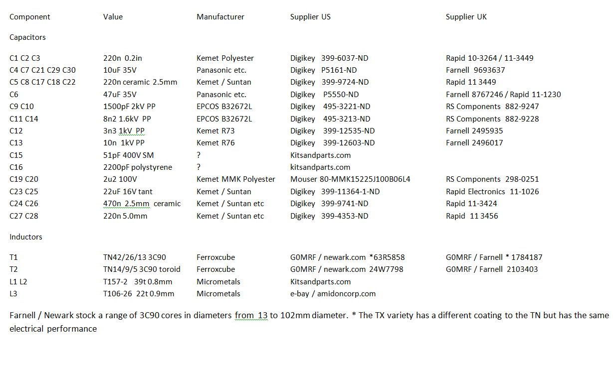
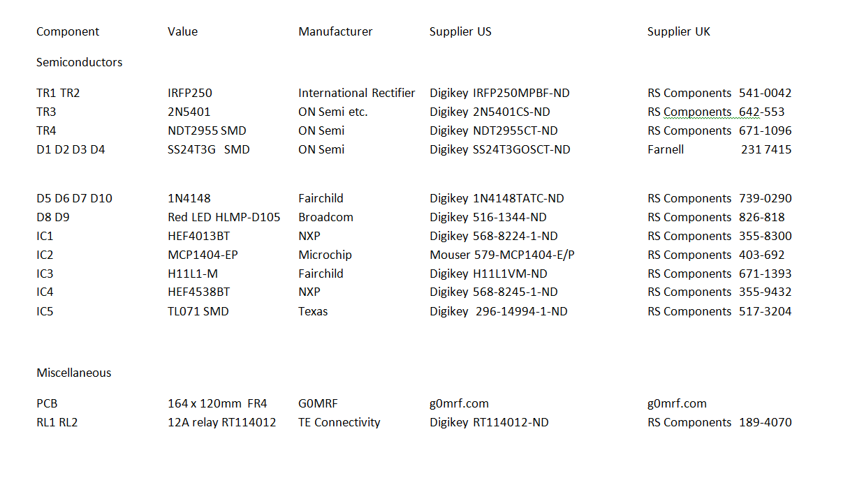
This page is a work in progress and presents additional information on the 630m amplifier project including a component list and some details on performance. If constructors come across any ‘features’ or make any suggestions for modifications, then those comments will be added to this page.
Component
list.
The component list for the amplifier is presented below. I have attempted to
find sources for each component here in Europe, but also in the USA.
The Digikey part numbers presented are a
‘best endeavour’ on my part so please check that each suggested part
number matches the description before you order. – Should you discover any
errors please let me know at g0mrf(at)aol.com
Having said that there are
not many parts that are critical to the design and so you may be able to find
suitable components around your shack / junk box.
Components I would suggest that should not be changed are:
1) The LEDs D8 and D9 used for indicating current and VSWR trips. – These
are low current devices and normal 20mA LEDs will not work correctly.
2) The FET driver IC2
3) The CMOS ICs IC1
and IC4. These should be the
HEF40xx series from NXP as they have been tested extensively for drive /
triggering / and rise and fall times.
With other manufacturers, performance may be subtly different.

Updates:
13/Sept/16.
1) R23 / R24 - Note fig.2 on main page shows these two resistors incorrectly fitted.
(positions reversed)
2) 100nF decoupling capacitors changed to 220nF. - Only reason was to reduce
the numbers of different values. No difference in performance.
19/Sept/16
3) The PCB has a small silk screen error. In the row of 5 connections near
RV3, the pads marked CUR LMT and REF LMT are reversed. These are the +ve
feeds to the LEDs that indicate the cause of a fault. If wired as shown the
protection circuits work but the LED for indicating a VSWR trip will
illuminate when the current trip has been triggered.
23/Jan/17
3) Update to circuit diagram. T1 Secondary now 16 turns instead of
15t. / Q4 now changed to read TR4.
On component list above. R23 (12k) and R24 (100k) now correctly
listed and consistent with circuit diagram. Digikey part number
corrected for TR4
Thanks to John WA3ETD (WG2XKA) and Steve KK7UV (WH2XNV) for these updates
Constructing the directional coupler
The
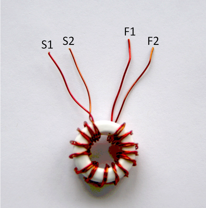
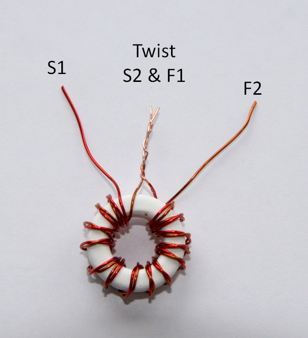
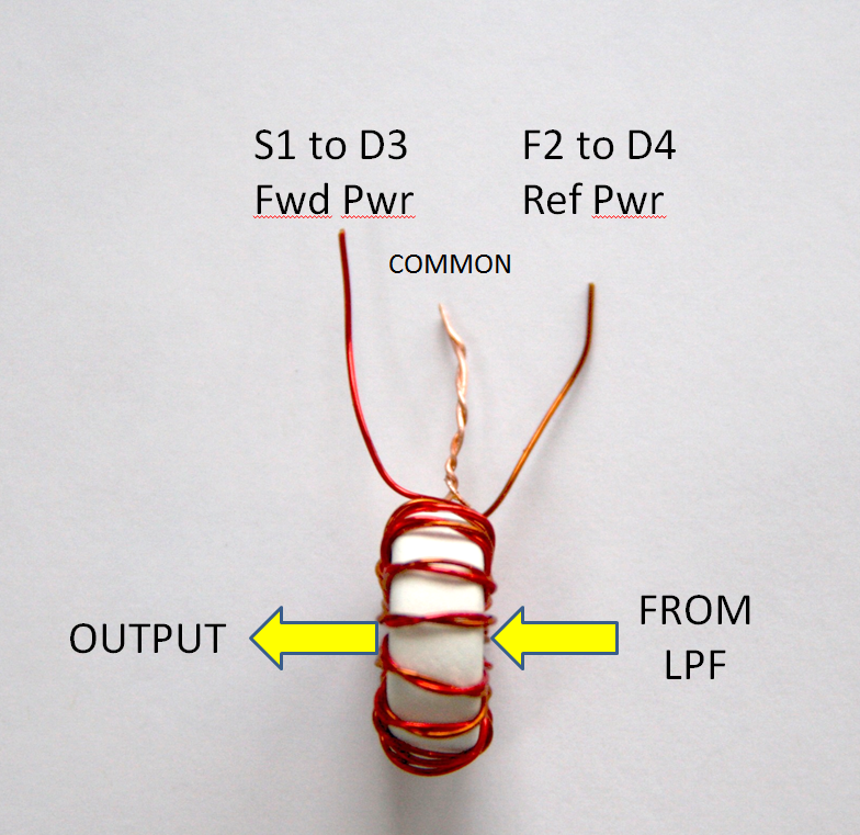
three images below show the construction of the directional coupler. Start by
twisting two lengths of 28 SWG enameled wire together. Wind 15 turns onto the
toroid core as shown in the fist image on the left and separate the windings
so you can identify the Start and Finish of each one.
Next, remove the enamel from S2 and F1 with a sharp knife and twist
together as shown in the middle photo and solder.
Finally, rotate the core as shown in the final photo on the right and remove
the enamel from the remaining wires. Note that S1 emerges from the
middle of the core on the right, then runs across the core so it can be
connected to the forward power connection (D3). Making sure the windings
are correctly oriented is important as the protection circuits need to work on
detected reverse power...not forward power. If you follow the method
described, all will be fine. Before soldering the completed directional
coupler to the board you need to prepare a short length of wire for the
primary winding which passes through the middle of the core. I used a short
piece of the inner from RG58 coax. Hold the coupler in place then pass the
RG58 inner through it. When soldered to the PCB the RG58 inner (apx 4mm dia
with its insulation) holds the coupler nicely in place. Then you can trim the
coupler wires to size and solder to the 3 pads on the board. If you anticipate
using your amplifier portable, you may want to use the smallest amount of
epoxy glue to hold it in place to prevent vibration damage when traveling.
Performance:
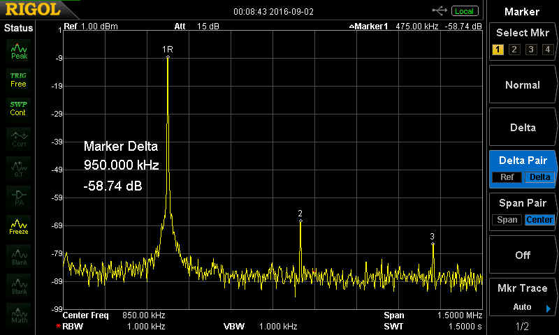
The FCC in the USA requires all harmonics to be reduced to a
minimum of 55dB below the wanted signal. The
image below demonstrates that the second harmonic is around 58dB down while
the 3rd harmonic is 66dB below the wanted signal.